國立屏東大學 資訊工程學系 物件導向軟體工程
2. UML簡介
UML的全名為Unified Modeling Language (UML)。
- UML is a standardized general-purpose modeling language in the field of object-oriented software engineering.
- UML is managed and was created by Object Management Group (OMG).
- Current version is 2.3 (May 2010)1)
- UML includes a set of graphic notation to create visual models.
- Visual Modeling是透過模型和標準的圖示標記來思考真實世界問題處理的方法
- UML也是UP所採用的視覺化(圖形化)的Modeling Language。
- Visual Modeling是透過模型和標準的圖示標記來思考真實世界問題處理的方法,
- UML是用來支援許多系統的視覺化模組語言。
- 本身在設計上混合了現今最佳的建模技術與軟體工程
- 其優點便是它很容易被理解,並且可以輕易地透過電腦繪製出來。
- UML本身是不含任何建構模型的方法論。
- UML不是方法論─它是一種統一的視覺塑模語言,而UP才是方法論。
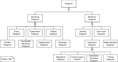
2.1 UML Diagrams
2.1.1 Structure diagrams
Structure diagrams emphasize the things that must be present in the system being modeled. Since structure diagrams represent the structure, they are used extensively in documenting the software architecture of software systems
2.1.1.1 Class diagram
軟體存在的目的就是為了滿足使用者的需求。
此處所謂的使用者需求,係指在特定情況、場所、時間等條件下,使用者需要軟體幫助完成的工作項目或是實現的目標。例如一個學生,在開學前兩週到開學後一週內,需要網路選課軟體的幫助來完成新學期課程的選修;又例如一個銀行帳戶的擁有者,需要一個智慧型行動電話的APP軟體來幫助他(她)完成跨行轉帳的需求;同一個例子還可以衍生到銀行業務的監管單位,他們會需要一個軟體來即時監測全國各個銀行同時進行中的跨行轉帳,並從其中攔截疑似洗錢的轉帳活動。在軟體開發初期,開發人員必須要透過訪談、實地觀察、資料收集等手段,儘可能地瞭解使用者的需求為何,然後才是依據需求進行軟體的設計與開發,以回應使用者的需求。在前述的例子當中,我們必須要瞭解與學校選課相關的辦法與規定,例如各系所開課程的明細、學生修業的規定、選修課程學分的上限與下限等細節;另一方面,學生也希望網路選課軟體可以支援包含IE、Chrome、Safari在內的不同瀏覽器,當然這也是網路選課軟體的使用者需求之一。我們通常將使用者的需求分成兩類:功能性需求(Functional Requirements)與非功能性需求(Non-Functional Requirements)。
功能性需求係指軟體為滿足使用者需求所提供的功能或服務,包含了資料的輸入、輸出、處理、計算等細節以及其它使用者希望軟體提供的功能。以網路選課軟體為例,其功能性需求包含了如何讓使用者瀏覽或依條件查詢課程、進行選課、預覽選課結果、選修學分不足的警示、選修學分過多的錯誤處理、選修課程衝堂警示,以及這些功能執行時的使用者介面等。
非功能性需求則是與軟體功能無直接相關的要求或限制,包含系統建置或運行的要求、開發軟體的工具或程式語言、必須遵循的規範、標準或法規、安全性、可靠性的要求等。以網路選課軟體為例,支援IE、Chrome、Safari等多種瀏覽器就是一種與功能無直接相關的非功能性需求;又或者為了要和既有的系統相容,所以我們被要求搭配MySQL資料庫來進行資料相關的儲存、查詢與處理,也是非功能需求的一個例子。
<作業:針對銀行跨行轉帳的APP軟體,指出其功能性與非功能性需求>
在前述的幾個簡單的例子中,這些軟體又常被稱為客製化(Customized)軟體,係針對特定的(已知的)使用者、特定的用途所開發。另一方面,有時候軟體並不是為了滿足特定的(已知的)使用者的需求,而是針對特定目標市場潛在的使用者族群進行設計與開發,此類軟體又被稱為通用型(Generic)軟體,通常會公開向所有潛在的使用者販售。舉例來說,電玩軟體就是通用型的軟體,它是針對可能有興趣的使用者所設計開發,有時無法滿足每一個使用者的需求。當然,如果你本身就是一個程式設計師,你可以專門為你的小孩設計一個專屬的電玩軟體,這種情況就是屬於客製化的軟體。通用型的軟體有時可以選定一些具代表性的使用者進行需求瞭解,來制定其使用者需求,或是完全有開發人員自行假設使用者的各種可能的需求。簡言之,這兩類的軟體主要的差別在於,客製化的軟體是針對明確已知的使用者及其需求客製化設計開發,通用型的軟體則是由軟體開發者自行預想使用者可能的需求而加以設計開發;就如同量身定製的西裝和大量生產的成衣西裝的差別。
<作業:請就你所知,分別就客製化與通用型的軟體各舉出兩個實例,並說明其功能性與非功能性需求>
使用物件導向技術所開發的軟體,在執行時會建構出一個虛擬的物件導向世界,其中包含有對應於真實或虛擬世界的人、事、時、地、物的抽象物件,透過物件與物件、物件與使用者的互動,來滿足使用者的需求。
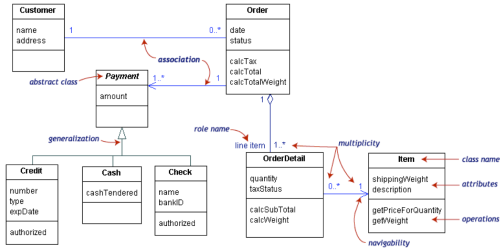
類別圖(Class Diagram)是用以描繪軟體的靜態結構的工具之一,它是用以描述軟體所建構出的虛擬物件導向世界中所包含的物件分別屬於哪些類別,其中包含各類別的屬性(Property)與操作(Operation),以及類別間的關聯性(Association)、關係(Relationship)與限制(Contraint),以下將分別加以說明。
在類別圖中,類別(Class)是以一個矩形加以表達,其中又可進一步分為三個區段,分別用以定義一個類別的名稱、屬性以及其操作。請參考下圖
圖中顯示了在我們欲建構的物件導向世界中,將會存在Painter類別的物件,其類別名稱為Painter(如圖中矩形的第一個區段所標示的)。至於第二個區段即為該類別所擁有的屬性,其中每一個屬性用一行文字定義,其語法如下:
visibility name: type multiplicity = default {property-string}
- visibility:屬性的可見性,例如Java語言中的public與private,其中以+號表示public、以-號表示private。
- name:屬性的名稱,例如在Java語言中的類別變數(Class Variable)的名稱,意即在該類別中可使用的變數之名稱。
- type:屬性的型態,通常為該變數的資料型態,當然也可以是類別名稱(意即為該類別之物件)。
- multiplicity:多元性,我們將在後續章節再加以解釋。
- default:意即該屬性的預設值。
- property-string:該屬性性質的定義,我們也將在後續章節再加以解釋。
要注意的是,這些定義的內容並不是每一項都必須寫明,其中只有name是必要的,其它的項目是可以省略的。現在,讓我們再以Painter類別為例,使用下面這張圖將該類別的屬性加以定義:
首先要說明的是,不一定需要將所有的類別變數都加入到圖中,僅需要將未來實作時比較重要的變數納入即可,有一些相對不重要的變數不需要加入到類別圖中。目前我們將兩個在Painter.java中已定義的類別屬性放在圖中,分別是用以定義軟體標題與用以儲存已建立的繪圖頁(Page)的Vector類別的物件加入其中。如同圖中所呈現的,這兩個屬性都是public的變數,其名稱分別為title與pages,其中title的型態定義為String,pages則定義為Vector<Page>(這代表pages是Vector類別的物件,且其所儲存的是Page類別的物件),另外title的預設值在圖中已加以給定,pages則沒有加以給定。
再說明第三個區段前,讓我們先介紹類別間的關聯(Association),請參考下圖:
我們現在將另一個重要的類別Page也加入到圖中,讓程式設計師瞭解除了Painter類別外,還必須實作Page類別(為簡化起見,目前Page類別中的屬性與操作都先加以省略)。雖然程式設計師可以透過在Painter類別中的pages屬性瞭解到一個Painter類別的物件會包含有多個Page類別的物件(定義在Painter類別中的pages屬性),但從圖中並沒有辦法直觀地呈現這一點。因此,我們將透過使用類別圖中的關聯,來修改該圖,請參考下圖:
2.1.1.2 Component diagram
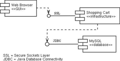
It describes how a software system is split up into components and shows the dependencies among these components.
2.1.1.3 Composite structure diagram
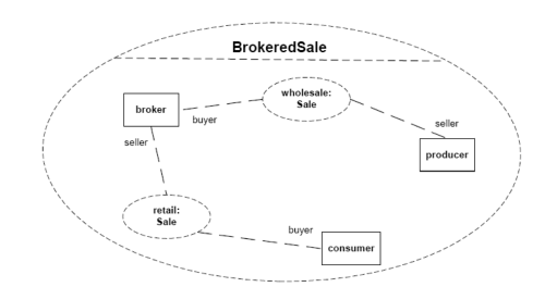
It describes the internal structure of a class and the collaborations that this structure makes possible.
2.1.1.4 Deployment diagram
It describes the hardware used in system implementations and the execution environments and artifacts deployed on the hardware.
 Fig. 5: an example deployment diagram
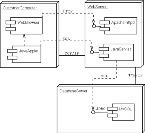 Fig. 6: an example deployment diagram with component diagrams
2.1.1.5 Object diagram
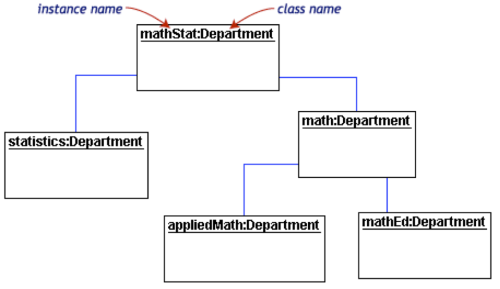
It shows a complete or partial view of the structure of an example modeled system at a specific time.
2.1.1.6 Package diagram
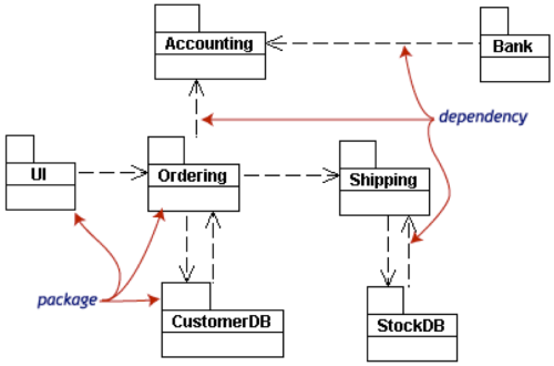
It describes how a system is split up into logical groupings by showing the dependencies among these groupings.
2.1.1.7 Profile diagram
It operates at the metamodel level to show stereotypes as classes with the «stereotype» stereotype, and profiles as packages with the «profile» stereotype. The extension relation (solid line with closed, filled arrowhead) indicates what metamodel element a given stereotype is extending.
2.1.2 Behavior Diagrams
Behavior diagrams emphasize what must happen in the system being modelled. Since behavior diagrams illustrate the behavior of a system, they are used extensively to describe the functionality of software systems.
2.1.2.1 Activity diagram
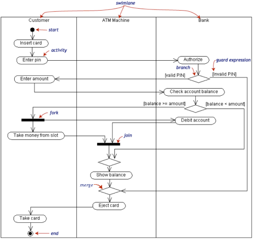
It describes the business and operational step-by-step workflows of components in a system. An activity diagram shows the overall flow of control.
2.1.2.2 Statechart diagram
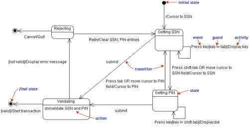
It describes the states and state transitions of the system.
2.1.2.3 Use case diagram
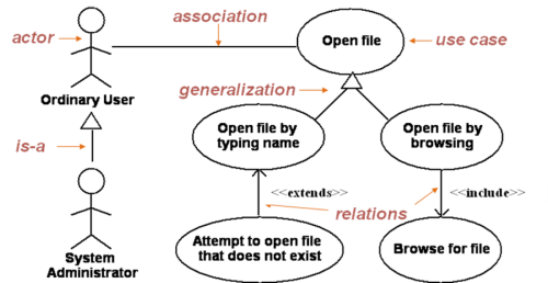
It describes the functionality provided by a system in terms of actors, their goals represented as use cases, and any dependencies among those use cases.
2.1.2.4 Interaction diagrams
A subset of behavior diagrams, emphasize the flow of control and data among the things in the system being modelled:
2.1.2.4.1 Communication diagram
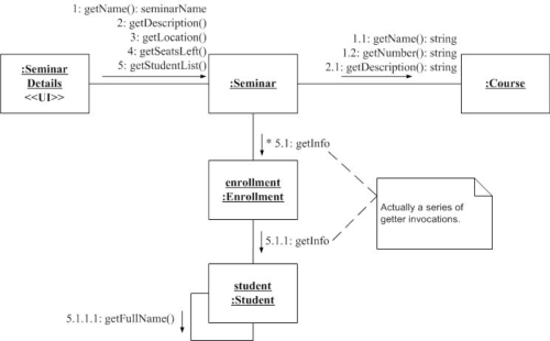
It shows the interactions between objects or parts in terms of sequenced messages. They represent a combination of information taken from Class, Sequence, and Use Case Diagrams describing both the static structure and dynamic behavior of a system.
2.1.2.4.2 Interaction overview diagram
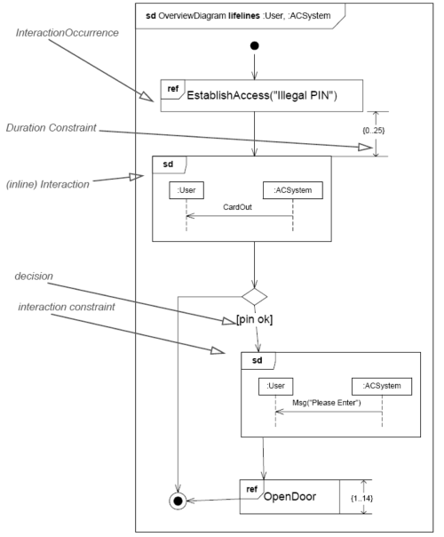
It provides an overview in which the nodes represent communication diagrams.
2.1.2.4.3 Sequence and Collaboration diagrams
Sequence diagram shows how objects communicate with each other in terms of a sequence of messages. Also indicates the lifespans of objects relative to those messages. Collaboration diagram is another equivalent diagram.
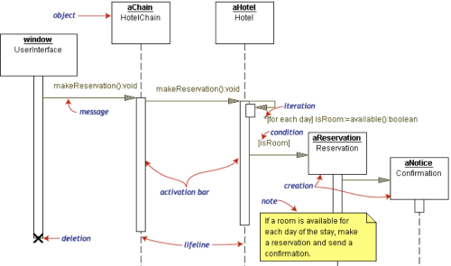 Fig. 15: an example sequence diagram
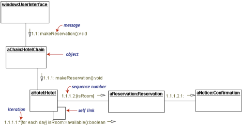 Fig. 16: an example collaboration diagram
2.1.2.4.4 Timing diagram
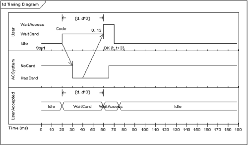
A specific type of interaction diagram where the focus is on timing constraints.
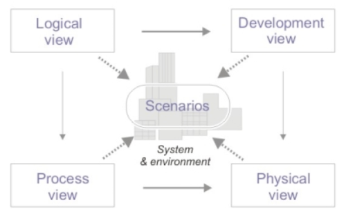
2.1.3 4+1 Views
When looking at an entire system as a whole, it can seem complicated at first and a good starting point if to create a 4+1 model diagram by breaking it down into 5 parts or Views. This model ensures you have considered and documented these 5 high level important aspects of any system. This approach breaks down the modeling of any system into the following views (inclusive of a use case view):
Views are used to describe the system from the viewpoint of different stakeholders, such as end-users, developers and project managers.
2.1.3.1 Logical View: The system objects
- The logical objects (parts) of the system.
- This view shows the components (objects) of the system as well as their interactions / relationships. So effectively is the object model layout. It comprises the classes and objects within the system.
- The logical view is concerned with the functionality that the system provides to end-users.
- UML diagrams:
- Class Diagrams (Most common UML diagram)
- State Diagrams
- Object Diagrams
- Sequence Diagrams
- Communication Diagrams
2.1.3.2 Process view: The System Workflow
- The process (workflow) of operation of these objects.
- The process view shows the processes / workflow rules of a system and how those processes communicate with each other. It explores ‘what needs to happen’ in a system.
- The process view deals with the dynamic aspects of the system, explains the system processes and how they communicate, and focuses on the runtime behavior of the system. The process view addresses concurrency, distribution, integrators, performance, and scalability, etc.
- UML Diagrams: Activity diagram.
2.1.3.3 Physical view (/Deployment view): The System Environment
- The physical hardware and software the systems runs on.
- The physical view depicts the system from a system engineer's point-of-view. It is concerned with the topology of software components on the physical layer, as well as the physical connections between these components.
- This view shows the systems execution environment (hardware / software platforms).
- UML Diagrams: Deployment diagram.
2.1.3.4 Development view (/Implementation view): The packages, run-time environments and class libraries used
- The packages, run-time environments and class libraries used.
- The development view illustrates a system from a programmer's perspective and is concerned with software management.
- UML Diagrams: Component diagram、Package diagram.
2.1.3.5 +1 view - use cases or scenarios
- Use cases view (also called Scenarios view)
- What the system does (functionality) from the perspective of a user (scenarios). Used in combination with requirement / specification documents.
- The description of an architecture is illustrated using a small set of use cases, or scenarios which become a fifth view.
- The scenarios describe sequences of interactions between objects, and between processes. They are used to identify architectural elements and to illustrate and validate the architecture design.
- They also serve as a starting point for tests of an architecture prototype.
- UML Diagram(s): Use case diagram.
